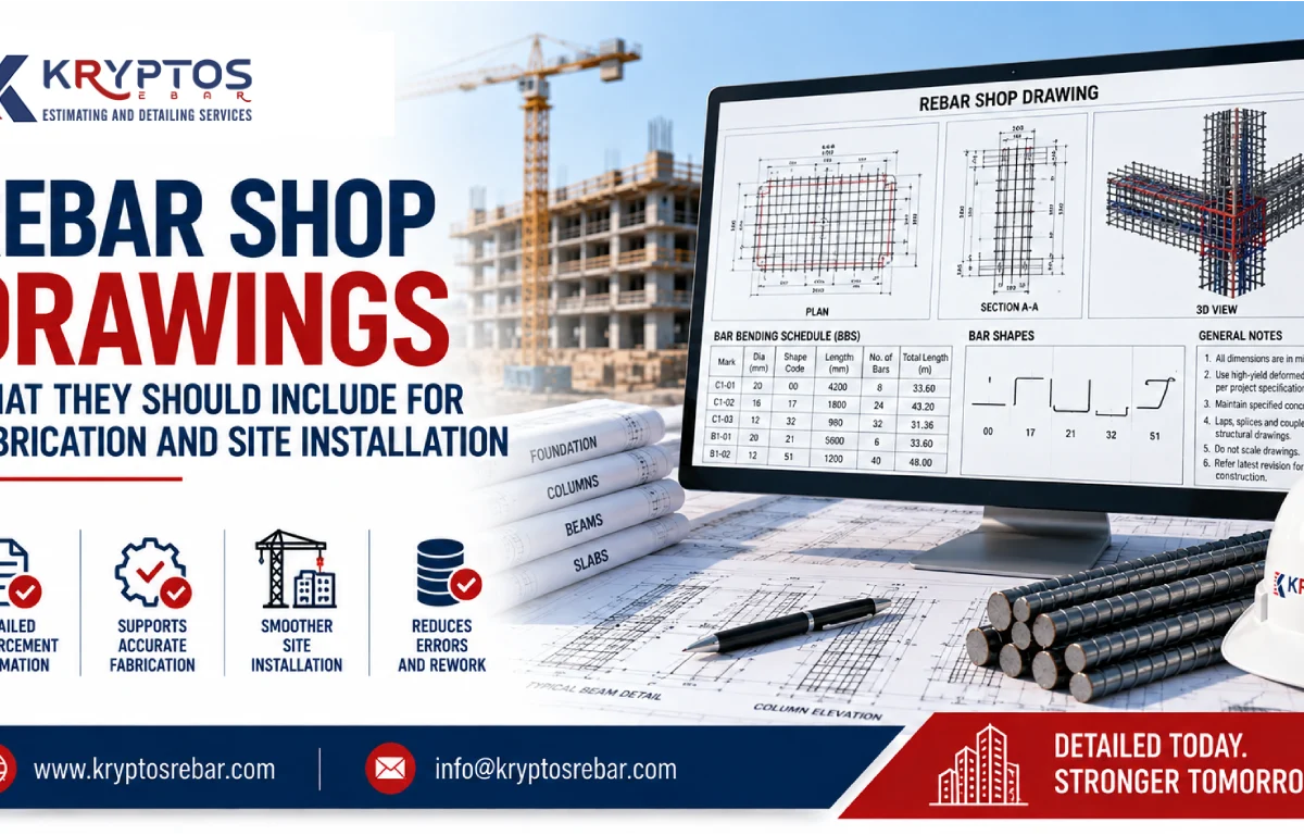




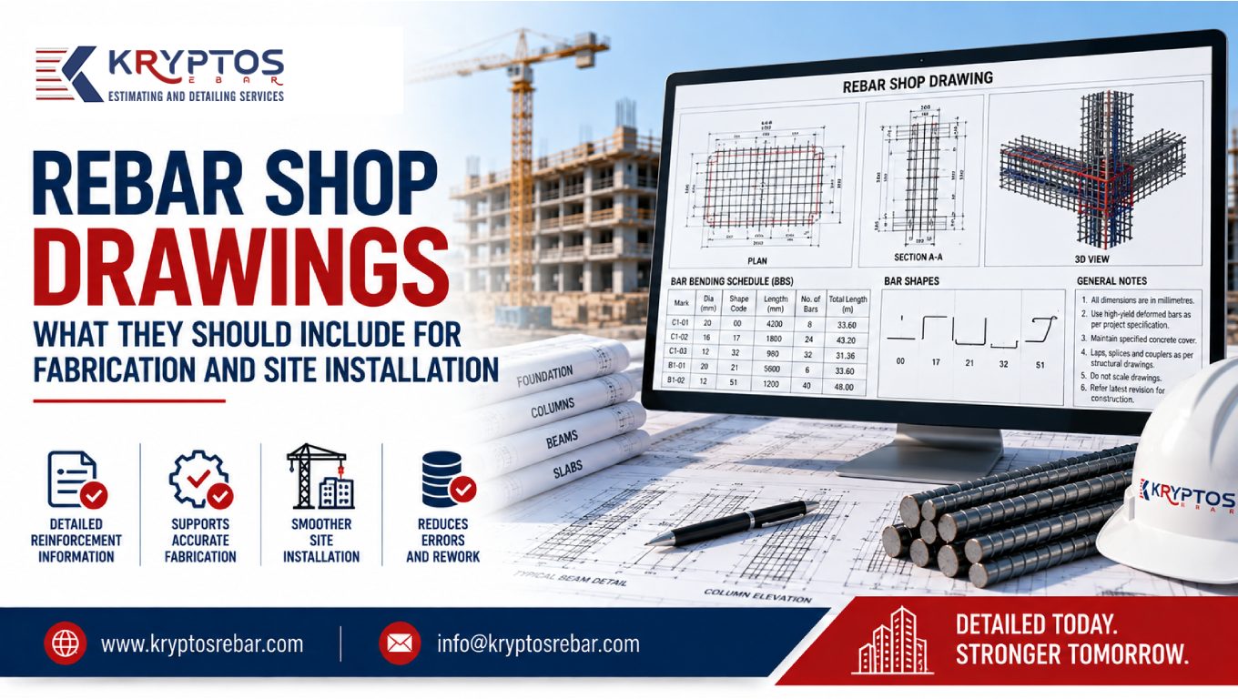
Rebar Shop Drawings: What They Should Include for Fabrication and Site Installation
Rebar shop drawings are an important part of reinforced concrete construction because they translate structural design information into detailed reinforcement documentation that fabricators and site teams can use.
Structural drawings communicate the engineer’s design intent, but construction teams often need more detailed information to fabricate and install individual reinforcement bars.
This is where rebar shop drawings become valuable.
A well-prepared drawing can show the location, size, spacing, shape, quantity, and arrangement of reinforcement within structural elements. It can also provide sections, elevations, bar marks, notes, and other information needed to understand how reinforcement should be fabricated and installed.
For complex projects, the importance of clear reinforcement documentation increases significantly. Multistoried buildings, foundations, transfer structures, shear walls, core walls, and heavily reinforced beam-column joints may contain complicated reinforcement arrangements that are difficult to interpret from general structural drawings alone.
This guide explains what rebar shop drawings should contain, how they support fabrication and site installation, common mistakes to avoid, and how a coordinated detailing workflow can improve reinforcement documentation.
👉 Rebar Detailing Services
kryptosrebar.com/service/
What Are Rebar Shop Drawings?
Rebar shop drawings are detailed reinforcement drawings prepared to communicate how reinforcing steel should be fabricated and placed within a concrete structure.
They typically provide information such as:
1.Bar marks
2.Bar sizes
3.Bar spacing
4.Bar lengths
5.Bar shapes
6.Reinforcement locations
7.Sections and elevations
8.Lap and splice information
9.Concrete cover
10.Quantity information
11.Construction joints
12.Opening reinforcement
13.General notes
The exact content and level of detail can vary depending on the project, structural design, applicable standards, client requirements, and fabrication workflow.
The primary purpose is to provide clear and coordinated reinforcement information that can support fabrication and installation.
Why Rebar Shop Drawings Matter
Reinforcement is not simply placed according to the overall shape of a concrete element.
Individual bars may have different:
1.Diameters
2.Lengths
3.Shapes
4.Spacing
5.Bend configurations
6.Locations
7.Anchorage requirements
Without clear documentation, fabricators and installers may have difficulty identifying the exact reinforcement required.
Well-coordinated rebar shop drawings can help project teams:
1.Understand reinforcement arrangements
2.Fabricate bars accurately
3.Identify reinforcement locations
4.Coordinate different structural elements
5.Verify quantities
6.Identify potential congestion
7.Support site installation
8.Reduce unnecessary clarification requests
They also provide a common reference between detailing teams, fabricators, contractors, engineers, and site personnel.
9 Essential Details Rebar Shop Drawings Should Include
1. Bar Marks and Identification
Every reinforcement bar or bar type should have a clear identification system.
Bar marks allow the same reinforcement to be tracked between:
Shop Drawing → Bar Bending Schedule → Fabrication → Delivery → Site Installation
For example, a drawing may identify a particular reinforcement type using a unique bar mark.
The corresponding BBS can then provide its:
1.Diameter
2.Quantity
3.Shape
4.Cutting length
5.Weight
Consistent bar marking reduces confusion and makes reinforcement easier to track.
2. Bar Diameter and Grade
Drawings should clearly identify the required reinforcement size.
Depending on project requirements, reinforcement information may also need to identify the applicable reinforcement grade or material specification.
This information should be consistent with the approved structural design and project specifications.
A mismatch in reinforcement size can have significant structural implications, so bar diameter should be carefully checked during quality control.
3. Bar Spacing
Spacing is particularly important for reinforcement distributed across slabs, walls, foundations, and other structural elements.
Drawings should clearly communicate:
1.Bar spacing
2.Direction
3.Starting locations
4.End conditions
5.Additional reinforcement zones
For example, slab reinforcement may be specified at a particular spacing in two directions.
Clear dimensioning helps installers understand the intended reinforcement arrangement.
4. Bar Length and Shape
Fabricators need accurate information about the geometry of each reinforcement bar.
A shop drawing should communicate the required bar shape through dimensions, bar geometry, or references to the corresponding BBS.
Bent reinforcement may include:
1.Hooks
2.Cranks
3.U-bars
4.L-bars
5.Closed links
6.Stirrups
7.Other project-specific shapes
Clear shape information helps reduce ambiguity during fabrication.
5. Reinforcement Locations
One of the primary purposes of rebar shop drawings is to show where reinforcement should be installed.
Drawings should clearly identify reinforcement within:
1.Footings
2.Columns
3.Beams
4.Slabs
5.Walls
6.Stairs
7.Pile caps
8.Core walls
9.Transfer structures
Plans, elevations, sections, and enlarged details can be used depending on the complexity of the element.
6. Sections and Enlarged Details
Some reinforcement arrangements cannot be communicated effectively through plan views alone.
Sections and enlarged details are particularly useful for:
1.Beam-column joints
2.Core walls
3.Shear walls
4.Transfer beams
5.Deep beams
6.Footings
7.Congested reinforcement zones
A well-developed section can show the relationship between multiple layers of reinforcement.
This can help installers understand which bars are positioned at the top, bottom, inside, outside, or between other reinforcement layers.
7. Lap Splices, Couplers, and Anchorage
Reinforcement continuity often requires laps, mechanical couplers, or other approved connection arrangements.
Where applicable, shop drawings should clearly identify the relevant locations and information based on the approved structural design.
This may include:
1.Lap locations
2.Lap lengths
3.Coupler locations
4.Starter bars
5.Development information
6.Anchorage details
These details should not be assumed by the fabricator or installer.
They should be coordinated with the applicable structural design and project requirements.
8. Openings and Additional Reinforcement
Structural and service openings can affect reinforcement arrangements.
Common openings include:
1.Doors
2.Windows
3.Stair openings
4.Elevator openings
5.MEP penetrations
6.Sleeves
7.Service shafts
Additional reinforcement may be required around certain openings.
Rebar shop drawings should clearly identify these conditions where they are part of the approved design.
Coordination with architectural and MEP information is particularly important for large or complex projects.
9. Concrete Cover and Reinforcement Positioning
Concrete cover is an important consideration in reinforcement detailing.
Shop drawings should communicate applicable cover requirements based on the approved structural design, project specifications, and relevant standards.
Drawings should also make reinforcement positioning clear enough for site teams to understand the intended arrangement.
Proper positioning can influence:
1.Durability
2.Structural performance
3.Reinforcement placement
4.Constructability
5.Concrete placement
Cover requirements should always be verified against the project’s governing requirements rather than assumed.
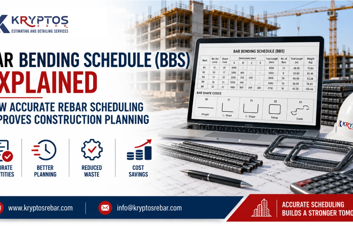
Rebar Shop Drawings and Bar Bending Schedules
Rebar shop drawings and Bar Bending Schedules (BBS) serve different but connected purposes.
The shop drawing primarily communicates where and how reinforcement is arranged.
The BBS provides detailed information about individual bars for fabrication and quantity control.
For example:
Shop Drawing:
Shows where Bar Mark B25 is installed in a beam.
BBS:
Provides information such as B25’s diameter, shape, quantity, cutting length, and weight.
Both documents should be coordinated.
If the shop drawing indicates 20 bars but the BBS lists 18, the discrepancy should be resolved before fabrication.
This is why drawing-to-schedule verification is an important quality-control step.
Rebar Shop Drawings and Fabrication
Fabrication teams use reinforcement documentation to manufacture individual bars.
The information provided should allow fabricators to understand:
1.What bars need to be produced
2.How many are required
3.What diameter they should have
4.What shape they should have
5.What length they should be
6.Where they will be used
Accurate fabrication information can reduce unnecessary rework and material discrepancies.
The fabrication workflow should also account for approved revisions.
If reinforcement is changed after fabrication information has been issued, affected drawings and schedules should be reviewed and updated before further production.
Rebar Shop Drawings and Site Installation
Once reinforcement is fabricated and delivered, site teams need to identify and place the bars correctly.
Clear shop drawings can support installation by showing:
1.Bar locations
2.Spacing
3.Bar marks
4.Reinforcement layers
5.Sections
6.Construction joints
7.Opening reinforcement
8.Lap locations
9.Additional bars
For repetitive buildings, bar marks can make it easier for installers to match delivered reinforcement with the correct floor or structural element.
Rebar Shop Drawings for Different Structural Elements
Foundation Shop Drawings
Foundation reinforcement drawings may include:
1.Bottom bars
2.Top bars
3.Distribution reinforcement
4.Starter bars
5.Column reinforcement
6.Pile cap reinforcement
7.Additional bars
Foundation drawings should make reinforcement layers and anchorage arrangements clear.
Column Shop Drawings
Column drawings typically communicate:
1.Vertical reinforcement
2.Ties
3.Bar sizes
4.Lap locations
5.Couplers
6.Starter bars
7.Level-to-level transitions
Vertical reinforcement continuity should be carefully coordinated.
Beam Shop Drawings
Beam reinforcement may include:
1.Top bars
2.Bottom bars
3.Side bars
4.Stirrups
5.Additional reinforcement
6.Anchorage details
Beam-column intersections often require additional sections.
Slab Shop Drawings
Slab drawings may show:
1.Top reinforcement
2.Bottom reinforcement
3.Main bars
4.Distribution bars
5.Support reinforcement
6.Opening reinforcement
7.Edge reinforcement
Wall Shop Drawings
Wall drawings may include:
1.Vertical reinforcement
2.Horizontal reinforcement
3.Boundary reinforcement
4.Opening reinforcement
5.Coupling beam reinforcement
6.Starter bars
Complex core and shear walls may require several sections and enlarged details.
Rebar Shop Drawings for Multistoried Buildings
Multistoried projects introduce additional coordination requirements.
Many floors may have similar structural layouts, but variations can occur at:
1.Podiums
2.Transfer floors
3.Mechanical floors
4.Roof levels
5.Structural transitions
6.Core openings
A typical floor should therefore not be copied without checking its specific structural requirements.
For repetitive elements, standardized detailing can improve consistency, while floor-specific review ensures that local changes are not overlooked.
Rebar Congestion and Shop Drawing Coordination
Reinforcement congestion occurs when multiple reinforcement bars occupy a limited space.
Typical congested areas include:
1.Beam-column joints
2.Transfer beams
3.Shear walls
4.Core walls
5.Heavily reinforced columns
6.Pile caps
Congestion should ideally be identified before fabrication.
3D reinforcement modeling can provide an additional way to review these areas.
Where a potential constructability issue is identified, the detailing team should coordinate with the responsible engineer and project team before making any structural change.
MEP Coordination
Reinforcement must often coexist with mechanical, electrical, and plumbing systems.
Potential conflicts can occur around:
1.Sleeves
2.Pipes
3.Ducts
4.Conduits
5.Embedded components
6.Service openings
For complex projects, multidisciplinary coordination can help identify these conflicts before reinforcement reaches the site.
BIM-based workflows can provide a shared environment for reviewing structural and building-service information.
buildingSMART International provides resources on openBIM and information exchange within the built environment.
BIM and Rebar Shop Drawings
Modern reinforcement detailing workflows increasingly use 3D modeling.
A digital reinforcement model can contain information about:
1.Bar diameter
2.Bar mark
3.Shape
4.Length
5.Location
6.Quantity
This information can support the production of shop drawings and schedules.
3D modeling can also help detailers review reinforcement intersections and identify potential clashes.
For reinforcement detailing workflows, Tekla Rebar Detailing provides information about model-based rebar detailing.
BIM should complement—not replace—engineering review and project-specific requirements.
Common Mistakes in Rebar Shop Drawings
Using Outdated Structural Drawings
Working from an old revision can cause the shop drawings to reflect superseded design information.
Missing Bar Marks
Unclear identification makes fabrication and installation more difficult.
Incorrect Dimensions
Incorrect lengths or spacing can result in fabrication and placement problems.
Incomplete Sections
Complex reinforcement may not be understandable from plans alone.
Poor Congestion Management
Dense reinforcement areas require additional review.
Drawing and BBS Mismatch
Both documents should be checked against each other.
Ignoring MEP Openings
Uncoordinated openings can create site conflicts.
Poor Revision Control
Updated design information must flow through all affected drawings and schedules.
Quality-Control Checklist for Rebar Shop Drawings
Before issuing rebar shop drawings, review:
1. Latest structural drawing revision used
2. Bar marks are consistent
3. Bar diameters verified
4. Spacing checked
5. Bar lengths reviewed
6. Shapes verified
7. Concrete cover checked
8. Laps coordinated
9. Couplers coordinated
10. Openings reviewed
11. Sections provided where required
12. Beam-column joints reviewed
13. MEP coordination completed where applicable
14. BBS coordinated
15. Quantity information verified
16. Revision status confirmed
17. Independent quality review completed
How Accurate Rebar Shop Drawings Support Project Performance
The value of accurate shop drawings extends beyond drawing production.
They can support better coordination between:
Engineer → Detailer → Fabricator → Contractor → Site Team
When everyone works from coordinated reinforcement information, communication becomes more structured.
Accurate documentation can help reduce:
1.Fabrication ambiguity
2.Site clarification requests
3.Rework
4.Material discrepancies
5.Installation confusion
6.Revision-related errors
The exact project benefit will depend on the quality of the underlying design, coordination process, site execution, and other project factors.
How Kryptos Rebar Supports Rebar Shop Drawing Requirements
At Kryptos Rebar, we provide professional rebar shop drawings designed to support reinforcement fabrication, quantity control, coordination, and site installation.
Our services include:
1.Rebar shop drawings
2.Rebar detailing
3.Rebar estimation
4.Bar Bending Schedules
5.3D rebar modeling
6.Quantity verification
7.Constructability review
8.Revision management
9.Reinforcement coordination
Our workflow focuses on maintaining consistency between structural information, reinforcement models, shop drawings, schedules, and quantity reports.
This helps project teams maintain clearer reinforcement documentation from design through fabrication and installation.
Best Practices for Preparing Rebar Shop Drawings
For consistent results, project teams should:
Start With Approved Information
Use the latest available structural drawings and specifications.
Maintain Consistent Bar Marking
The same bar identification should be maintained across drawings, BBS, fabrication, and installation.
Provide Sufficient Detail
Use plans, sections, elevations, and enlarged details where necessary.
Coordinate Before Fabrication
Review reinforcement against architectural, structural, and MEP information.
Verify Quantities
Compare drawing quantities with BBS and estimation outputs.
Track Revisions
Maintain clear revision records and update affected documents.
Perform Independent QC
A second review can identify errors before documents reach fabrication.
Conclusion
Rebar shop drawings provide a practical connection between structural design and reinforcement fabrication and installation.
A well-prepared drawing should communicate much more than the location of reinforcing steel. It should provide clear information about bar marks, diameters, spacing, shapes, lengths, reinforcement locations, sections, laps, openings, concrete cover, and other project-specific requirements.
When shop drawings are coordinated with rebar detailing, Bar Bending Schedules, quantity estimates, BIM models, and constructability reviews, project teams can establish a more consistent reinforcement workflow.
The most important principle is simple:
The reinforcement information used for fabrication should be clear, coordinated, current, and traceable back to the approved structural design.
For complex projects, investing time in detailed coordination and quality control before fabrication can help reduce avoidable discrepancies during manufacturing and site installation.
Frequently Asked Questions
1. What are rebar shop drawings?
Rebar shop drawings are detailed reinforcement drawings that communicate the size, shape, quantity, spacing, location, and arrangement of reinforcing steel for fabrication and site installation.
2. What should rebar shop drawings include?
They commonly include bar marks, bar sizes, spacing, dimensions, bar shapes, reinforcement locations, sections, concrete cover, laps, openings, and other project-specific reinforcement details.
3. What is the difference between structural drawings and rebar shop drawings?
Structural drawings communicate the engineer’s structural design. Rebar shop drawings provide more detailed reinforcement information intended to support fabrication and installation.
4. Are rebar shop drawings and BBS the same?
No. A BBS focuses on individual bar information such as quantity, shape, length, and weight, while shop drawings primarily communicate reinforcement placement and arrangement. They should be coordinated.
5. How do rebar shop drawings help fabrication?
They provide fabricators with organized information about bar marks, sizes, shapes, lengths, quantities, and other requirements needed to produce reinforcement.
🚀 Need Accurate Rebar Estimation You Can Trust?
Connect with Kryptos Rebar for precision-driven rebar detailing, estimation, and constructability-focused reinforcement solutions.
📩 Email now: [email protected]
Let’s optimize your structure with precision and confidence.