



Construction Joint Reinforcement: Detailing Essentials
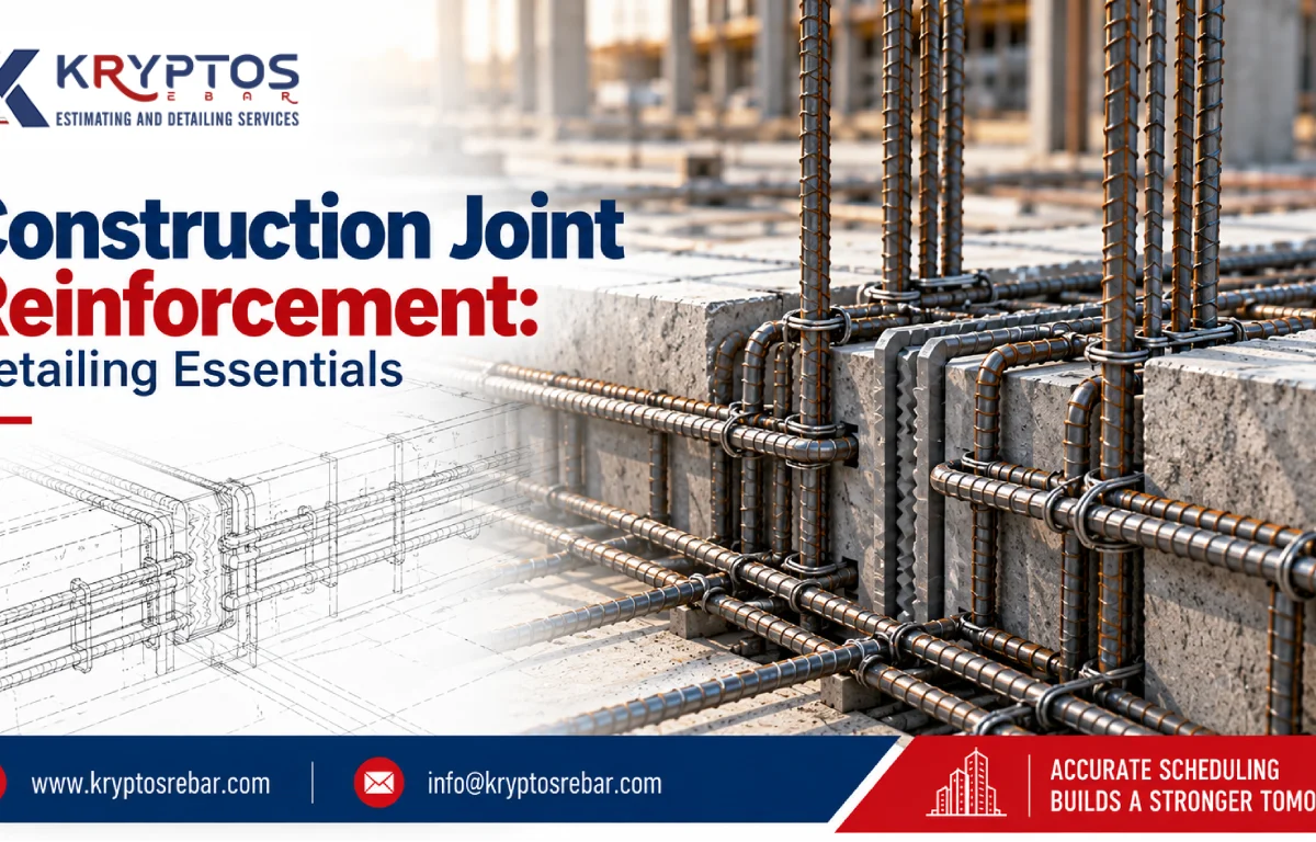
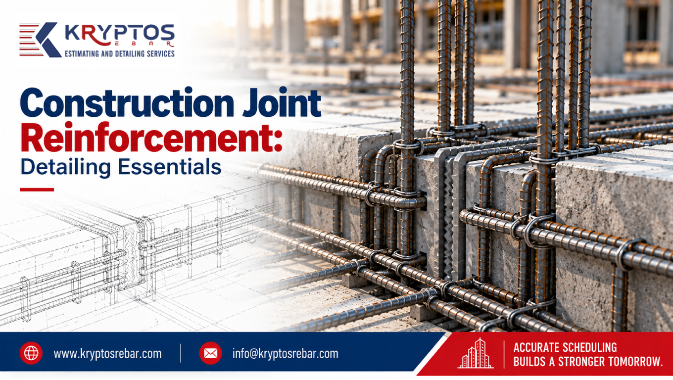
Construction joint reinforcement is an important consideration in reinforced concrete construction because it helps maintain the intended structural behavior where concrete placement is interrupted. Construction joints are commonly required when a concrete pour cannot be completed continuously because of project sequencing, site conditions, work schedules, or practical construction limitations. These joints must be planned carefully to ensure that reinforcement, concrete preparation, and joint locations follow the approved structural design.
Accurate detailing helps contractors understand how reinforcing bars should continue through or terminate at a construction joint, where laps and anchorage are required, and how reinforcement should be positioned for concrete placement. Clear drawings also help reduce site confusion, reinforcement clashes, material waste, and costly rework. At Kryptos Rebar, we recognize the value of coordinated reinforcement documentation in supporting efficient construction planning and reliable site execution.
👉 Rebar Detailing Services
kryptosrebar.com/service/
What Is Construction Joint Reinforcement?
Construction joint reinforcement refers to the reinforcing steel arrangement associated with a planned interface between separate concrete placements. A construction joint is created when one section of concrete is placed and allowed to harden before the adjoining section is poured. The joint may occur in a slab, beam, column, wall, foundation, or other reinforced concrete element.
The reinforcement arrangement depends on the structural design, the location and orientation of the joint, loading conditions, and the applicable building code. In many situations, reinforcing bars continue across the joint to provide the required force transfer and structural continuity. In other situations, the engineer may specify particular bar terminations, dowels, couplers, or other connection details.
It is important to understand that reinforcement alone does not automatically ensure a satisfactory construction joint. Joint surface preparation, concrete placement procedures, and any specified shear-transfer measures must also follow the approved design and project specifications.
Why Construction Joint Detailing Matters
Construction joint detailing translates structural design requirements into practical instructions for reinforcement fabrication and installation. Incomplete or unclear details can lead to incorrect bar placement, insufficient development length, reinforcement congestion, and delays during concrete placement.
Well-prepared details help coordinate reinforcement with formwork, embedded items, openings, and adjoining structural elements. They also allow estimators and procurement teams to identify the required bar sizes, shapes, lengths, and quantities before materials are ordered.
Key benefits of accurate construction joint detailing include:
1.Structural coordination: Helps ensure that reinforcement arrangements match the approved engineering design.
2.Installation clarity: Shows bar continuity, termination points, laps, anchorage, and other specified details.
3.Quantity accuracy: Supports reliable reinforcement takeoffs and bar bending schedules.
4.Reduced rework: Helps identify drawing discrepancies and potential clashes before construction.
5.Improved planning: Supports pour sequencing, fabrication scheduling, and coordination between project teams.
The structural engineer remains responsible for establishing the required joint design and reinforcement provisions. Detailers must represent those requirements accurately rather than independently changing the structural arrangement.
Essential Reinforcement Detailing Considerations
1. Rebar Continuity Across Construction Joints
Rebar continuity at construction joints is one of the primary detailing considerations. Where the design requires reinforcement to continue across the joint, the drawings should clearly show the bar size, spacing, direction, location, and required continuation into the adjoining concrete placement.
Detailers should verify whether bars are continuous, lapped, mechanically coupled, or arranged using specified dowels. The detail must reflect the structural drawings and approved connection requirements. Bar ends should not be shortened, relocated, or terminated simply to make the concrete pour easier.
For slabs and walls, the drawings should identify the reinforcement layers and show how bars pass through the joint area. For beams, columns, and foundations, the details should coordinate longitudinal bars, transverse reinforcement, and any required anchorage. Clear section views are particularly useful where multiple reinforcement layers meet.
2. Lap Splices and Development Length
Lap splices and development length must be detailed in accordance with the governing design documents and applicable code requirements. A lap splice transfers force between reinforcing bars through the surrounding concrete, while development length provides the embedment required to develop the specified bar force.
The required lengths can depend on several factors, including bar diameter, concrete strength, steel properties, cover, spacing, confinement, coating, and the applicable code provisions. Therefore, a single standard lap length should not be assumed suitable for every construction joint.
Detailing teams should identify splice locations, required lengths, and any restrictions stated in the structural drawings. Where the design specifies mechanical couplers or alternative connections, the drawings should show the correct system and its location. Any missing or conflicting requirements should be referred to the structural engineer for clarification before fabrication or installation.
3. Anchorage and Bar Termination
Anchorage is another essential aspect of construction joint reinforcement. Reinforcing bars must have the required embedment, hooks, bends, or approved mechanical anchorage to develop the forces assumed in the structural design. Incorrect bar termination can compromise the intended load path and create difficulties during installation.
Construction joint details should show where reinforcement begins and ends, whether bars extend into the next pour, and how the specified anchorage is achieved. Hooks and bends must follow the approved bar shape and detailing requirements, including applicable bend diameters and clearances.
Where reinforcement terminates near a joint, detailers should verify that the design provides the required anchorage and force transfer. If the structural drawings do not clearly define the arrangement, the detailer should raise a request for information rather than assume a solution.
4. Joint Location and Pour Sequencing
Construction joint locations should follow the structural design and approved construction sequence. The location may be influenced by structural behavior, pour size, access, formwork, equipment, and site logistics. Moving a joint without the required engineering approval can affect the intended performance of the concrete element.
Reinforcement drawings should coordinate the joint location with bar continuity, splice locations, construction access, and formwork arrangements. They should also make it clear which reinforcement belongs to each concrete placement where separate pours are involved.
For large slabs, retaining walls, foundations, and other extensive concrete elements, coordinated pour plans and reinforcement details can help site teams understand the sequence of work. If a proposed pour break conflicts with reinforcement or approved joint locations, the issue should be resolved with the responsible engineer before work proceeds.
Construction Joint Reinforcement in Different Concrete Elements
Construction joint detailing varies according to the type of structural element and its design requirements.
Slabs and Floor Systems
In slabs, details may need to show top and bottom reinforcement, bar continuation, splice positions, edge conditions, and any specified dowels or additional bars. The drawing should also coordinate the joint with openings, embedded services, and changes in slab thickness.
Beams and Columns
Beam and column joints require careful coordination of longitudinal reinforcement, stirrups, ties, confinement reinforcement, and bar congestion. The detail should reflect the structural design and show how the reinforcement is arranged around the joint without compromising required spacing or concrete placement access.
Walls and Retaining Structures
Wall construction joints may involve vertical and horizontal reinforcement, dowels, waterstops, and other specified joint components. In retaining walls and water-retaining structures, joint location and waterproofing requirements may be especially important. These provisions must be coordinated with the structural design and relevant project specifications.
Foundations and Raft Slabs
Foundation joints require coordination between reinforcement layers, starter bars, column or wall connections, embedded items, and the planned concrete pour sequence. Accurate detailing helps the site team position reinforcement correctly before the next placement and avoid conflicts with formwork or other foundation components.
The specific requirements for each element must be established by the responsible design team. These examples are general detailing considerations, not substitutes for project-specific engineering instructions.
Coordination Between Reinforcement Drawings and Site Requirements
Construction joint reinforcement should be coordinated with other project information before the drawings are issued for fabrication. A detail that appears correct in isolation may still create installation difficulties if it conflicts with formwork, embedded plates, sleeves, service penetrations, or adjacent reinforcement.
Effective coordination includes checking the structural drawings, reinforcement plans, sections, specifications, and approved revisions. Where Building Information Modeling (BIM) is used, coordinated models may help identify physical clashes and congested areas, although model checks do not replace engineering review.
Important coordination checks include:
1.Confirming that the joint location matches the approved drawings and pour plan.
2.Checking bar spacing, concrete cover, anchorage, and splice requirements.
3.Reviewing reinforcement clashes near openings, embeds, and adjoining elements.
4.Verifying bar marks, bending shapes, quantities, and drawing references.
5.Recording unresolved discrepancies and obtaining the necessary design clarification.
These checks are particularly valuable in complex projects where multiple teams work on structural design, reinforcement fabrication, and site installation at the same time.
Common Construction Joint Reinforcement Detailing Mistakes
Several detailing problems can create avoidable delays, material waste, or quality concerns. Identifying these issues before fabrication helps project teams resolve them at the right stage.
Common mistakes include:
1.Showing reinforcement continuation without clearly indicating the required embedment or connection arrangement.
2.Using assumed lap lengths without checking the approved design and applicable code.
3.Omitting required dowels, couplers, anchorage details, or transverse reinforcement.
4.Allowing joint locations to conflict with the approved construction sequence.
5.Failing to coordinate reinforcement with waterstops, embedded items, openings, or formwork.
6.Using outdated structural drawings or missing revision changes in the detailing package.
These problems can often be reduced through systematic drawing reviews, accurate bar schedules, revision control, and early communication with the structural engineering team. Any issue affecting structural adequacy must be referred to the responsible engineer for resolution.
How Rebar Detailing Services Support Construction Joint Accuracy
Professional reinforcement detailing services help translate approved engineering information into fabrication-ready and installation-ready documentation. For construction joints, this involves clearly representing reinforcement continuity, bar marks, splice arrangements, anchorage, dimensions, and connections to adjoining structural elements.
A coordinated detailing workflow generally begins with reviewing the latest structural drawings and specifications. The detailing team then develops the required plans, sections, and bar bending schedules, checks consistency across drawings, and records items that require clarification. Quantities can also be reviewed to support procurement and fabrication planning.
At Kryptos Rebar, our rebar detailing and estimation services support construction teams with reinforcement documentation and quantity planning. By emphasizing drawing clarity, coordination, and structured quality checks, we aim to help clients identify discrepancies earlier and prepare for more organized reinforcement fabrication and installation. All reinforcement details remain subject to the approved engineering design and project requirements.
Construction Joint Reinforcement Quality-Control Checklist
Before reinforcement drawings are released, a structured review can help identify missing information and inconsistencies.
Use this checklist as a general coordination aid:
1.Confirm that the joint location matches the latest approved structural drawings.
2.Verify bar sizes, spacing, direction, shape, and continuation requirements.
3.Check lap splices, development lengths, and anchorage against the design.
4.Confirm specified dowels, couplers, waterstops, and other joint components.
5.Review reinforcement cover, clear spacing, and installation access.
6.Coordinate reinforcement with formwork, embedded items, and service openings.
7.Check bar bending schedules, bar marks, quantities, and drawing revisions.
8.Refer unclear or conflicting structural requirements to the responsible engineer.
This checklist does not replace the project’s formal inspection and test plan, structural review, or site quality procedures. Construction joint preparation and concrete placement must also comply with the approved method statements and specifications.
Standards, Specifications, and Technical References
Construction joint reinforcement must be detailed in accordance with the structural design basis, project specifications, and applicable building codes. Requirements may differ depending on the jurisdiction, concrete element, loading conditions, and the role of the joint in the structural system.
Useful technical starting points include:
1.American Concrete Institute (ACI): https://www.concrete.org/ — publications and technical resources relating to concrete design and construction.
2.Autodesk BIM resources: https://www.autodesk.com/solutions/bim — information about model-based coordination and building information modeling.
3.Tekla: https://www.tekla.com/solutions/rebar-detailing — resources related to reinforcement detailing workflows.
These resources provide general technical and workflow information. The applicable code clauses and project-specific requirements should always be confirmed by the design team. Online summaries should not be used in place of the governing standard or approved construction documents.
Conclusion
Construction joint reinforcement is an important part of reinforced concrete detailing because it helps ensure that the steel arrangement at concrete interfaces reflects the intended structural design. Clear details for bar continuity, lap splices, anchorage, joint location, and pour sequencing can improve coordination between engineers, detailers, fabricators, and site teams.
A consistent review process also helps identify drawing discrepancies, reinforcement clashes, and missing information before fabrication or installation. By using the latest approved documents and referring structural uncertainties to the responsible engineer, project teams can improve documentation quality and reduce avoidable construction delays.
Frequently Asked Questions
1. What is construction joint reinforcement?
Construction joint reinforcement is the reinforcing steel arrangement specified at the interface between separate concrete placements. It may include continuous bars, lap splices, dowels, couplers, or other designed provisions, depending on the structural requirements.
2. Does reinforcement always need to continue across a construction joint?
No. The required arrangement depends on the structural design and the function of the joint. Reinforcement may continue across the joint or use a specified connection or termination detail. The approved structural drawings must determine the arrangement.
3. How are lap lengths determined at construction joints?
Lap lengths are determined using the applicable design code and project requirements. Factors can include bar size, concrete strength, reinforcement properties, cover, spacing, confinement, and splice conditions. Detailers should not use a universal lap length without verification.
4. What should construction joint reinforcement drawings include?
Depending on the project, they should identify the joint location, reinforcement sizes and spacing, bar continuation, splice and anchorage requirements, bar shapes and marks, relevant sections, and coordination with specified joint components and adjoining elements.
5. Who approves construction joint reinforcement details?
The responsible structural engineer or authorized design professional establishes or approves the structural requirements. Reinforcement detailers prepare drawings based on the approved design and raise questions when information is missing or conflicting. Contractors must follow the approved documents and project procedures.
🚀 Need Accurate Rebar Estimation You Can Trust?
Connect with Kryptos Rebar for precision-driven rebar detailing, estimation, and constructability-focused reinforcement solutions.
📩 Email now: [email protected]
Let’s optimize your structure with precision and confidence.